Product Gallery
Ultra-Thin Sheets, Die-Cut to Your Antenna
Flexible ferrite sheets from 0.05 mm, standard rectangles or kiss-cut on a liner to your coil outline — bare, PSA-backed or double-sided tape, ready for your assembly line.
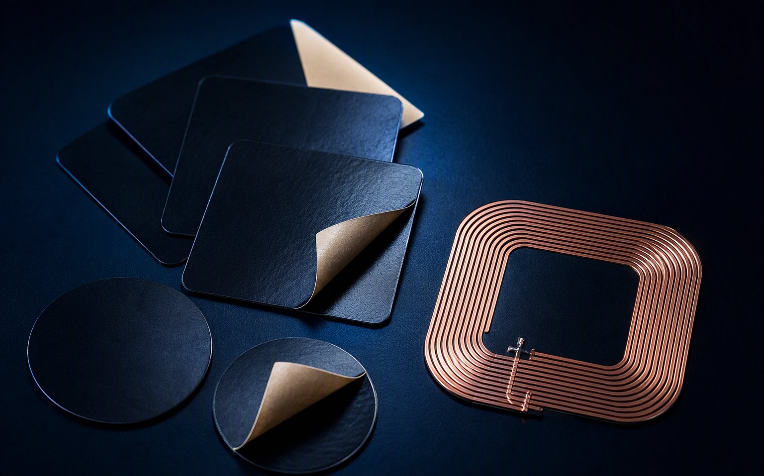
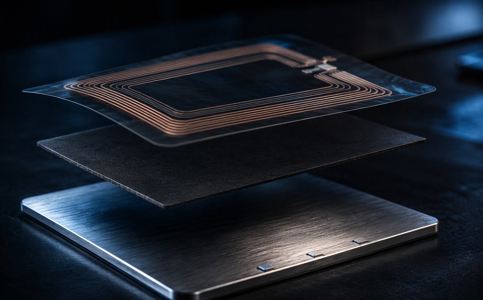
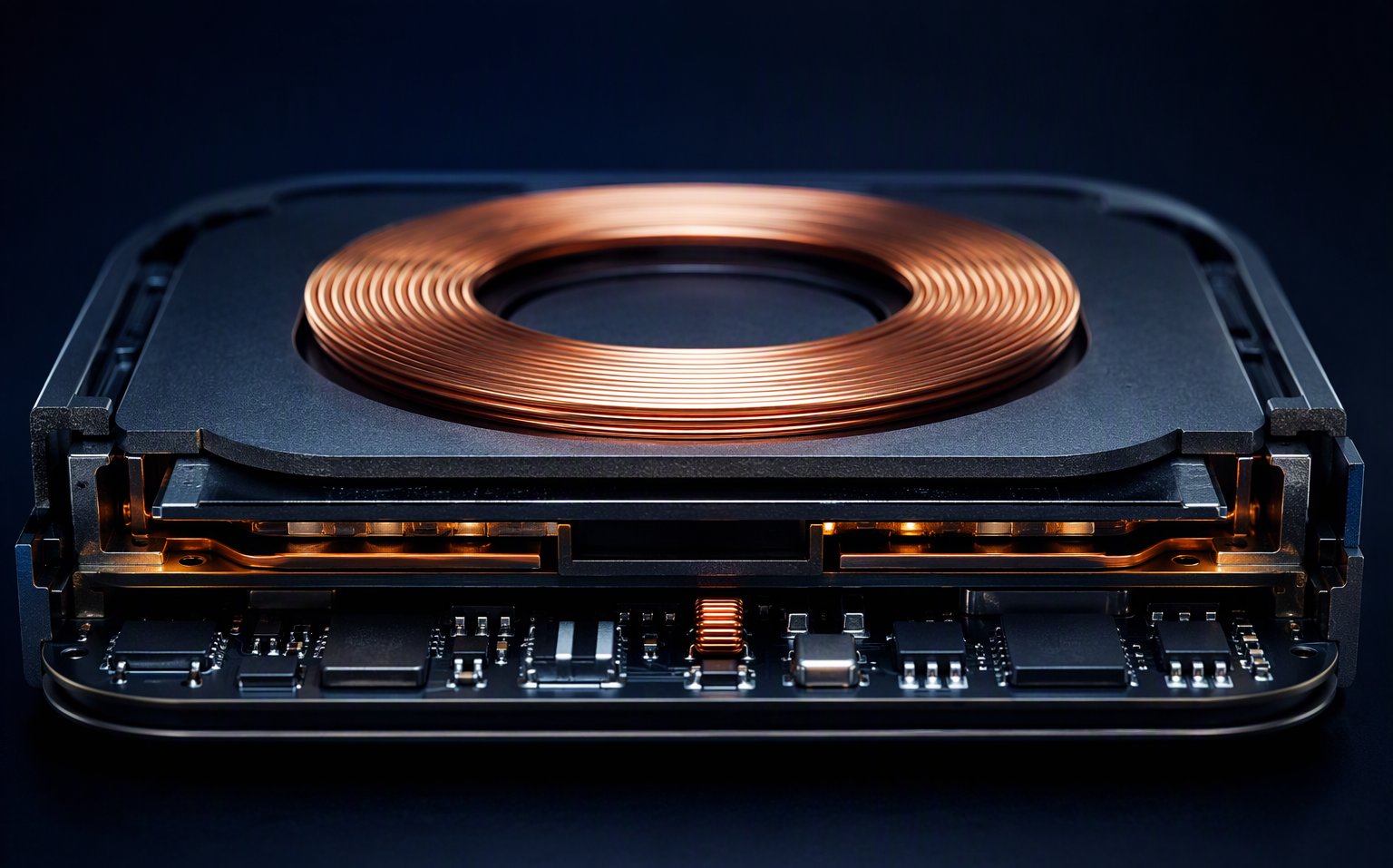
A 13.56 MHz antenna mounted near metal loses most of its range to eddy currents. A correctly chosen ferrite sheet redirects the flux and restores it — but only if the permeability, thickness and outline match your antenna. We supply XAK-NFC series ferrite sheets (13.56 MHz) and XAK-WPT wireless-charging sheets (Qi 87–205 kHz, Qi2 MPP 360 kHz), die-cut to your drawing, with adhesive backing, in prototype and production quantities. Response within 24 hours.
Flexible ferrite sheets from 0.05 mm, standard rectangles or kiss-cut on a liner to your coil outline — bare, PSA-backed or double-sided tape, ready for your assembly line.
Four failure patterns we see when the ferrite sheet is treated as an afterthought instead of a designed component.
The prototype read at 4 cm on the bench. In the housing, against a battery or chassis, read range collapses. Metal isn't blocking the signal — eddy currents are detuning your antenna, and no amount of antenna redesign fixes that alone.
Two black sheets look identical but do opposite jobs. An NFC ferrite sheet is a flux redirector — high permeability, low loss at 13.56 MHz. An EMI absorber sheet is high-loss by design. Put an absorber behind your NFC antenna and it eats the field you were trying to save.
0.05 mm and 0.30 mm sheets are not interchangeable: thinner fits tighter gaps but redirects less flux. Choosing by "whatever fits" instead of by measured read range leaves performance on the table — or adds thickness you didn't need.
Your antenna isn't a 55×85 mm rectangle. A sheet that doesn't cover the coil — or overhangs into a display flex — costs you range and assembly yield. The sheet should be cut to your antenna, not the other way around.
We treat the ferrite sheet as part of your antenna circuit — because electrically, it is.
NFC at 13.56 MHz, Qi at 87–205 kHz, Qi2 MPP at 360 kHz, UHF at 868/915 MHz — each band wants a different permeability-loss balance. We match the material grade to your frequency, not to a shelf.
Tell us the available gap behind the antenna and your current read range. We recommend the thinnest sheet that restores your target — typically 0.05–0.15 mm for space-critical devices, 0.2–0.3 mm where performance leads.
Send a DXF or drawing and we kiss-cut sheets on a release liner with your choice of adhesive — PSA one side, double-sided tape, or bare. Sheets arrive ready for pick-and-place or manual assembly.
Standard sizes ship as free samples within days. Measure read range on your actual device, retune the matching network with the sheet in place, then lock the specification. That's the order that works.
Typical values for selection reference — final grade and thickness are confirmed against your antenna and measurement results.
| Product Family | Frequency Band | Thickness | Key Property | Typical Use |
|---|---|---|---|---|
| NFC ferrite sheet (flux director) | 13.56 MHz | 0.05–0.30 mm ferrite layer (≈0.10–0.40 mm total with PET + adhesive) | XAK-NFC series: μ′ 20 / 50 / 100 / 130 / 150 ±20%, low loss μ″ at 13.56 MHz | NFC/HF-RFID antennas on or near metal, payment wearables, access cards |
| Wireless charging ferrite (XAK-WPT) | 87–205 kHz (Qi 1.x), 360 kHz (Qi2 MPP) | 0.20–1.0 mm | Higher μ′ for strong flux concentration, characterized at 127.7 / 360 kHz, tight thickness tolerance | Qi / Qi2 TX/RX modules, magnetic charging docks, smartphone & wearable charging |
| On-metal tag sheet | 13.56 MHz / UHF 868–915 MHz | 0.10–0.50 mm | Flexible, bendable for curved asset surfaces | On-metal RFID labels, asset tags, smart packaging |
| EMI absorber sheet | 0.1–6 GHz | 0.10–1.0 mm | High magnetic loss — converts noise to heat | PCB noise suppression, cable/connector EMI, enclosure resonance damping |
The four application families behind most of our ferrite sheet projects.
Smartphones, payment wearables, smart locks and IoT sensors where the antenna sits millimeters from a battery or chassis. The ferrite sheet gives flux a low-reluctance path and the read range comes back — typically 70–90% of free-space performance after retuning.
Asset labels and access cards that must be readable when stuck on metal equipment. A flexible ferrite layer behind the inlay is the standard fix — we supply it die-cut to your label outline with the adhesive stack you specify.
Qi transmitter and receiver modules where the ferrite back plate concentrates coupling flux and shields the battery and PCB behind the coil. Thickness and permeability matched to your coil and target efficiency.
High-loss absorber sheets damping radiated noise at 100 MHz–6 GHz — over clock lines, connectors and enclosure seams. A different material family from NFC sheets; see our electronics & EMI applications.
What actually determines whether a ferrite sheet solves your problem.
The questions antenna and hardware engineers ask us most.
You don't need a finished specification. Send what you have — we'll recommend a grade and thickness with you.
Antenna details — coil dimensions or DXF, target frequency (13.56 MHz / Qi / UHF)
Space budget — available gap behind the antenna in mm
Metal environment — battery, chassis, shield can; distance from antenna
Performance target — current read range vs required read range
Quantities — sample needs and estimated annual volume
Timeline — when you need samples for bench testing
Share your antenna dimensions, gap and metal environment — we respond within 24 hours with a sheet recommendation and samples plan.
Request a Sheet Recommendation → info@xakmag.com