Product Gallery
From Magnet Segments to a Balanced Rotor
Surface-mount and interior-magnet rotors with carbon-fiber or metal retention sleeves, shaft-integrated assemblies, every unit flux-checked before it ships.
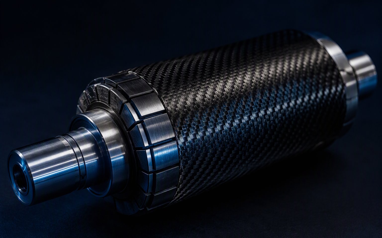
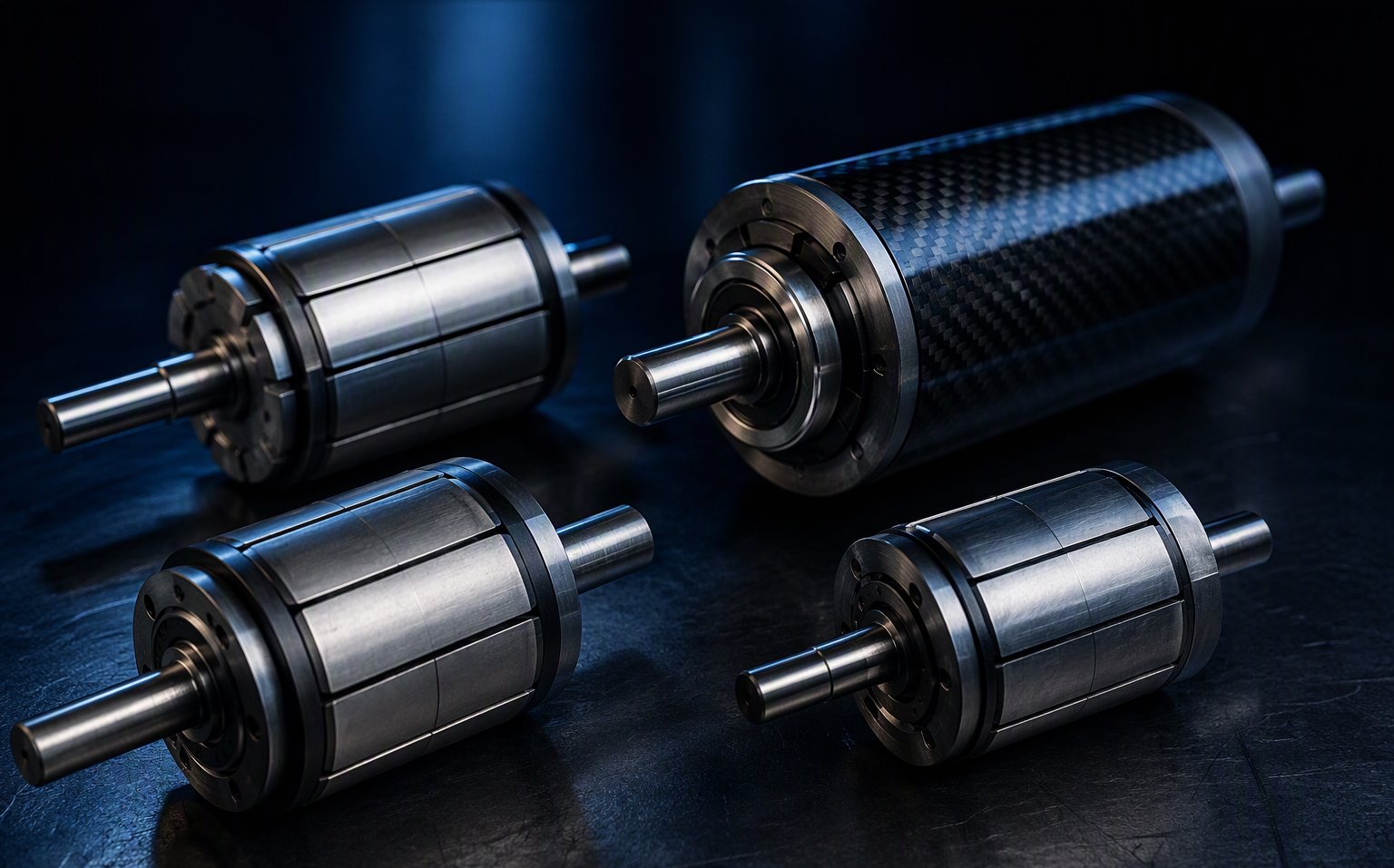
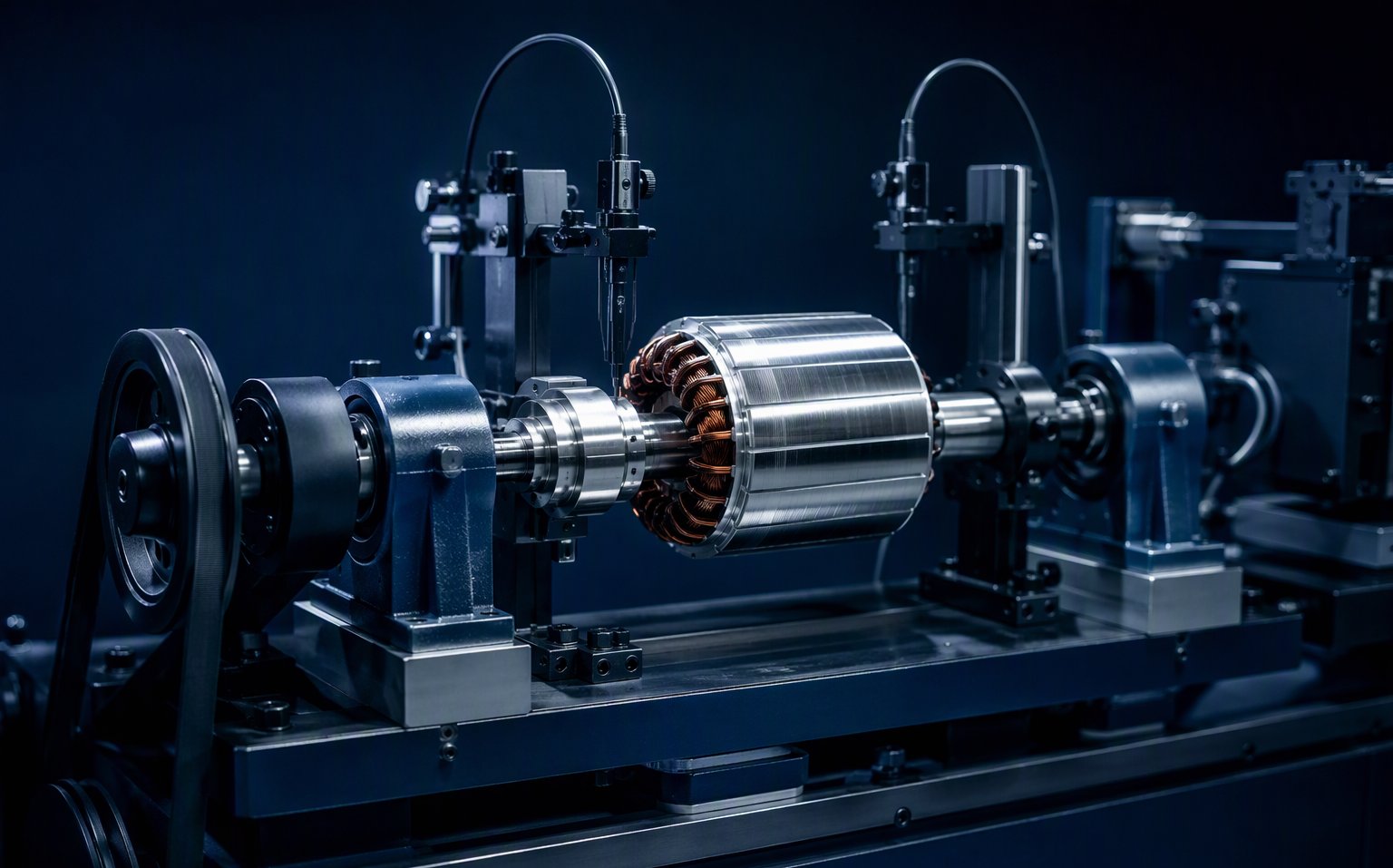
A rotor failure at speed is never just a magnet problem — it is retention, balancing, adhesive and grade selection failing together. We build complete PMSM/BLDC rotor assemblies to your drawing: magnets, shaft, sleeve, bonding and magnetizing — tested as one unit and shipped ready for your stator. Response within 24 hours.
Surface-mount and interior-magnet rotors with carbon-fiber or metal retention sleeves, shaft-integrated assemblies, every unit flux-checked before it ships.
Four failure patterns we see when a rotor is sourced as separate parts instead of an engineered assembly.
Adhesive alone is not a retention strategy. Above a few hundred meters per second of surface speed, centrifugal force peels bonded magnets off the core — usually during overspeed testing, sometimes in the field. Retention must be designed, not assumed.
A few gram-millimeters of residual unbalance at 20,000 rpm becomes a real force. Rotors balanced "good enough" at the magnet shop show up as vibration, noise and shortened bearing life in your motor — and the root cause is hard to trace afterward.
A rotor specified with standard N-grade NdFeB in a 150°C winding environment loses flux irreversibly within weeks. Grade selection must start from your worst-case temperature plus margin — not from the strongest grade on the shelf.
Magnet vendor, machine shop, balancing shop — when the assembly fails, each blames the other's tolerance. A rotor is a system: one drawing, one process chain, one party responsible for the final unit.
We take responsibility for the finished assembly — from magnet grade to the final inspection record.
Below ~150 m/s, bonded and mechanically keyed magnets suffice. Above that, pre-stressed carbon-fiber wound sleeves or shrink-fit metal sleeves (stainless, Inconel, titanium) carry the load. We size the sleeve from your speed, diameter and temperature — not from habit.
Balance and runout targets are locked into the drawing package before production — specify an ISO 21940 grade (G2.5 for industrial drives, G1 for high speed) or a residual unbalance in g·mm, and the assembly is built to meet it. Runout is always measured on the final assembly, not the bare shaft.
SH/UH/EH/AH-series NdFeB up to 230°C, SmCo for 250–350°C, ferrite where cost rules. We select from your peak winding temperature, demagnetization margin and duty cycle — then guarantee the grade on the certificate.
Segmented SPM rotors can be built from pre-magnetized arcs; multi-pole rings and IPM stacks are often safer magnetized post-assembly on our fixtures. We choose the route that hits your pole pattern and field uniformity target.
Typical values for selection reference — final design is always confirmed against your drawing, speed and temperature profile.
| Rotor Family | Topology | Typical Speed | Retention & Build | Typical Applications |
|---|---|---|---|---|
| High-speed SPM rotor | Surface-mounted arc magnets, inner rotor | 20,000–100,000+ rpm | Pre-stressed carbon-fiber wound sleeve or shrink-fit Inconel/titanium sleeve | Spindles, turbo compressors, eVTOL propulsion, flywheels |
| Standard SPM rotor | Surface-mounted arcs or bread-loaf magnets | up to ~20,000 rpm | High-temperature epoxy bonding + optional banding | Servo motors, pumps, fans, general BLDC |
| IPM rotor | Magnets embedded in lamination stack | up to ~15,000 rpm | Lamination bridges + adhesive potting; no sleeve needed | EV traction, compressors, field-weakening drives |
| Bonded ring rotor | Multi-pole bonded NdFeB / ferrite ring on shaft | up to ~30,000 rpm | One-piece ring, press-fit or bonded to shaft | Small BLDC, drones, hand tools, medical devices |
| Shaft-integrated sub-assembly | Rotor + shaft + encoder magnet + bearings seats | per design | Complete drop-in unit, balanced as one | Motor builders outsourcing the rotating group |
The four application families behind most of our rotor projects.
IPM and SPM traction rotors where torque density, field weakening and thermal margin decide the whole drive unit. Grade selection and balancing documentation are what your IATF audit will ask for.
Outrunner and inrunner propulsion rotors where every gram and every gram-millimeter of unbalance shows up in flight time and vibration. Bonded rings and carbon-sleeved SPM rotors dominate this space.
20,000 rpm and up, where retention sleeve design and G1 balancing are survival requirements, not options. Carbon fiber wound sleeves with verified pre-stress are our default route here.
Cost-sensitive volume rotors with tight cogging and back-EMF tolerances. See how we approach motor magnet systems on the electric motors application page.
The mechanics and magnetics we check before quoting any custom rotor.
What motor designers and sourcing engineers ask us most often.
No finished specification needed. Send what you have — we will engineer the rest with you.
Rotor drawing or sketch — DXF, PDF or STEP; NDA first if required
Motor data — power, rated & overspeed rpm, pole count, topology (SPM/IPM)
Envelope — rotor OD, shaft diameter, stack length, bearing journals
Thermal profile — worst-case winding/magnet temperature and duty cycle
Balance requirement — ISO 21940 grade or residual unbalance in g·mm
Quantities — prototype count, annual volume, target timeline
Share your drawing, speed and temperature targets — we respond within 24 hours with a retention and grade recommendation plus a prototype plan.
Request a Rotor Assessment → info@xakmag.com