Home  /  Applications  /  Tank Floor MFL

Tank Floor MFL Scanner Magnets, Magnetic Bridges & Structures

Component-level support for tank-floor corrosion screening scanners — permanent magnets, flux-return steel, sensor mounting and rugged mechanical structures designed around your scanner.

A Scanner Must Magnetize the Plate and Preserve Geometry While Moving

Tank-floor MFL combines a magnetic circuit with a moving mechanical platform. Plate condition, debris, coatings and scanning motion all influence the sensor environment.

Establishing a repeatable magnetic working point

Plate thickness and material, pole geometry and the magnetic return path determine whether the circuit can support useful metal-loss screening.

Maintaining lift-off across real plates

Coatings, weld profiles, plate steps, debris and scanner motion can change the sensor-to-plate gap. Mechanical guidance and wear parts matter.

Interpreting corrosion signals responsibly

MFL is a screening method. Top-side versus bottom-side discrimination and remaining-thickness sizing may require complementary sensing or ultrasonic verification.

Surviving field handling and contamination

The magnetic bridge attracts ferrous debris and the scanner sees repeated impact. Retention, cleaning access and replaceable protection must be engineered in.

A Moving Magnetic Bridge Screens for Local Metal Loss

The scanner magnetizes a local region of carbon-steel floor plate and reads disturbances in the flux as it travels. The diagram is schematic and not to scale.
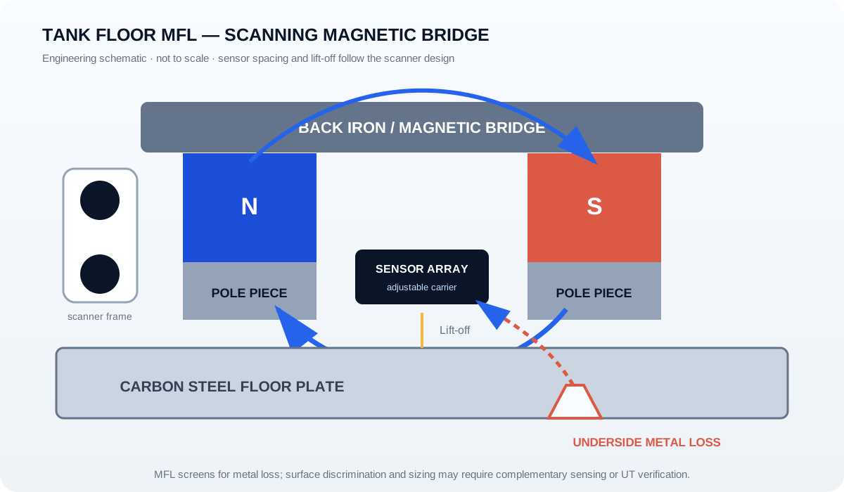
Tank floor MFL scanner magnetic bridge showing magnets, back iron, pole pieces, sensor array, floor plate and underside corrosion
A magnetic bridge guides flux through the plate; corrosion-related metal loss can create leakage signals at the sensor array.
  1. Create a local magnetic circuitPermanent magnets, pole pieces and back iron guide flux through the floor plate between the poles.
  2. Scan across the plateThe moving carriage carries the magnetizer and sensor array while attempting to maintain a consistent working gap.
  3. Detect leakage-field changesLocal metal loss changes the flux distribution; the sensor array records a response for the inspection system to process.
  4. Verify and classify as requiredThe inspection procedure may use additional sensors, visual checks or UT to distinguish surface origin and confirm remaining thickness.

What XAK Can Supply for Tank-Floor MFL Scanners

We support the magnetic bridge and its surrounding mechanical structure, with the supply scope split according to your drawings and assembly strategy.

01

Permanent magnet sets

NdFeB blocks or custom profiles supplied with defined grade, coating, polarity, magnetization direction and batch traceability.

02

Magnetic bridges and back iron

Steel return-path components and integrated bridge arrangements matched to the scanner’s pole spacing and available envelope.

03

Pole pieces and contact geometry

Machined pole components that shape the working region and interface with the plate-side wear system.

04

Sensor-array carriers

Brackets, carriers and adjustment features for customer-specified Hall or coil sensor layouts and lift-off targets.

05

Scanner frames and structural hardware

Supports, cross-members, spacers, handles, fixing details and retention structures supplied to the agreed mechanical scope.

06

Wear shoes and protective covers

Replaceable contact parts and non-magnetic protective elements where required, designed to support cleaning and maintenance.

Scope clarification: XAK supports scanner components and subassemblies, not tank inspection services or complete certified scanner performance. Detection thresholds, probability of detection and remaining-life assessment belong to the inspection system and procedure.

What MFL Can Screen — and What It Should Not Claim Alone

A useful component discussion must respect the limits of the inspection method as well as its strengths.

QuestionEngineering interpretationDesign / procedure implication
Can MFL screen for corrosion-related metal loss?Yes, it is widely used to screen carbon-steel tank floors for local magnetic-flux disturbances associated with metal loss.Calibration, scan coverage and signal processing remain system-level responsibilities.
Can basic MFL always separate top-side from bottom-side corrosion?No. Surface discrimination is not guaranteed by the magnetic bridge alone.Use complementary sensing and/or verification methods defined by the inspection procedure.
Does an MFL indication directly equal remaining thickness?Not without calibration and sizing procedures. Signal response depends on geometry, lift-off, material and defect form.Confirm selected indications with UT or another specified method where required.

Scanner specifications and acceptance criteria must come from the equipment designer and the applicable inspection procedure, not from a generic component page.

Structural design is magnetic design: a worn shoe, bent bracket or changed pole gap can alter both the magnetic working point and sensor lift-off. Wear limits and replacement interfaces should be included in the drawing review.

What to Send for a Useful Engineering Review

Drawings and operating conditions let us discuss the magnetic circuit and mechanical structure together. If some items are unknown, mark them as open rather than guessing.

Floor plateMaterial, thickness range, coating, weld profile and typical plate-step conditions.
Scanner architectureMagnetic bridge layout, pole spacing, scanning direction and available mechanical envelope.
Sensor arrangementSensor type, number and pitch of channels, carrier drawing and target lift-off.
Operating environmentDebris, liquid residue, temperature, cleaning method and expected handling loads.
Wear and serviceContact material, replaceable wear parts, adjustment method and maintenance access.
Supply and verificationMagnet-only or subassembly scope, drawing revision, quantities and agreed dimensional/magnetic checks.

Engineering FAQ

Does XAK provide tank-floor inspection services?

No inspection service is implied by this page. XAK supports magnetic and mechanical components for companies developing or manufacturing scanning equipment.

Can you supply the magnetic bridge with mechanical brackets?

Yes. The package can include magnets, back iron, pole pieces, sensor carriers, structural brackets, fixing details and wear-related parts according to the agreed drawing.

Can MFL alone identify whether corrosion is on the top or bottom surface?

Basic MFL should not be assumed to provide reliable surface discrimination by itself. The inspection system may need complementary sensing and UT or other verification.

Why are wear parts included in the magnetic design review?

Wear changes pole contact, working gaps and sensor lift-off. Those changes can affect the signal just as directly as a change in magnet grade.

Related Solutions

Discuss Your Component Requirements

Send your drawing, application conditions and target integration level. XAK will respond within 24 hours.

Contact →Request a Quote