Engineered magnetic and mechanical components for pipeline in-line inspection tools — from the magnet source and flux-return path to sensor mounting, retention and wear protection.
An ILI tool sees changing wall conditions, vibration, debris and repeated mechanical loading. Signal quality depends on the magnet circuit and on how consistently the tool holds its geometry.
Magnet grade, pole area, back iron and air gaps must be matched to pipe material and wall thickness. A larger magnet alone does not guarantee a cleaner leakage signal.
Wear, ovality, weld seams and vibration change the sensor-to-wall distance. Carrier geometry and compliant mounting are therefore part of signal stability, not just mechanical packaging.
Sensor type, tool speed and defect orientation affect the measured response. Axial and circumferential MFL configurations should be reviewed as different magnetic circuits.
Magnetization direction, pole-piece dimensions, assembly position and protective structures must remain consistent from prototype to replacement batches.
The illustration shows the component-level principle. It is an engineering schematic, not a validated tool design or a detection-performance claim.
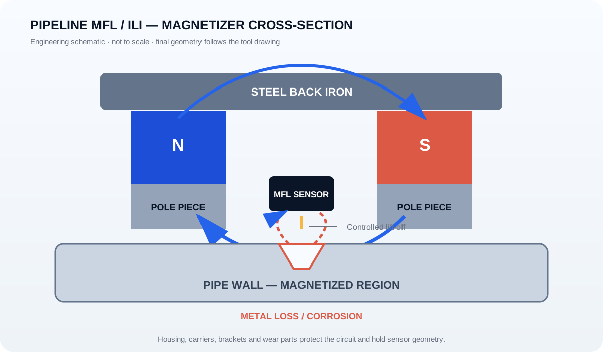
Supply can start with individual magnets or extend to drawing-based subassemblies. Material, geometry and inspection requirements are confirmed before production.
Custom blocks, arcs and matched magnet sets with defined grade, coating, magnetization direction and batch identification.
Steel parts machined to the drawing to guide flux and maintain the designed working gaps and contact geometry.
Integrated magnet + pole + return-path structures for axial or circumferential tool architectures.
Mechanical interfaces for Hall or coil sensor modules, with attention to position, lift-off and service access.
Stainless or application-appropriate housings, supports, spacers, fasteners and retention features built around your tool envelope.
Replaceable wear surfaces, covers and protective details that shield brittle magnets and help preserve sensor geometry.
Metal-loss features interrupt flux most effectively when their principal orientation crosses the magnetic flux. Tool architecture and the target anomaly set therefore determine the magnetizer layout.
| Configuration | Principal flux direction | Typical orientation sensitivity | Component implication |
|---|---|---|---|
| Axial MFL | Along the pipe axis | Often used for circumferentially oriented or transverse features | Magnetizer poles and return path are arranged around the axial field circuit. |
| Circumferential / transverse MFL | Around the pipe circumference | Often used for axially oriented or longitudinal features | The magnetization circuit and sensor layout are rotated to match the transverse field. |
Orientation sensitivity is tool- and procedure-dependent. Final detection capability must be established by the ILI system designer through calibration and validation.
Drawings and operating conditions let us discuss the magnetic circuit and mechanical structure together. If some items are unknown, mark them as open rather than guessing.
This page covers magnets, magnetic circuits, sensor-mounting parts and structural subassemblies. Complete tool electronics, inspection software and validated detection performance require a separate system-level scope.
Yes. XAK can coordinate magnet blocks, pole pieces, back iron, housings, brackets, fixing details and wear protection as a drawing-based supply package.
No single orientation should be assumed to cover every feature equally. Axial and circumferential systems respond differently; the target anomaly set and validation plan must guide the tool architecture.
Use a controlled drawing and revision, defined magnet grade and magnetization direction, critical steel-part dimensions, assembly datums and agreed batch inspection records.
Send your drawing, application conditions and target integration level. XAK will respond within 24 hours.
Contact →Request a Quote