Mount an NFC antenna directly on metal and read range collapses — sometimes from centimeters to millimeters. The fix is a thin ferrite sheet between antenna and metal. This guide covers why that works, how to choose thickness and permeability, and the mounting details that decide whether the fix actually performs.
Why Metal Kills Your NFC Antenna
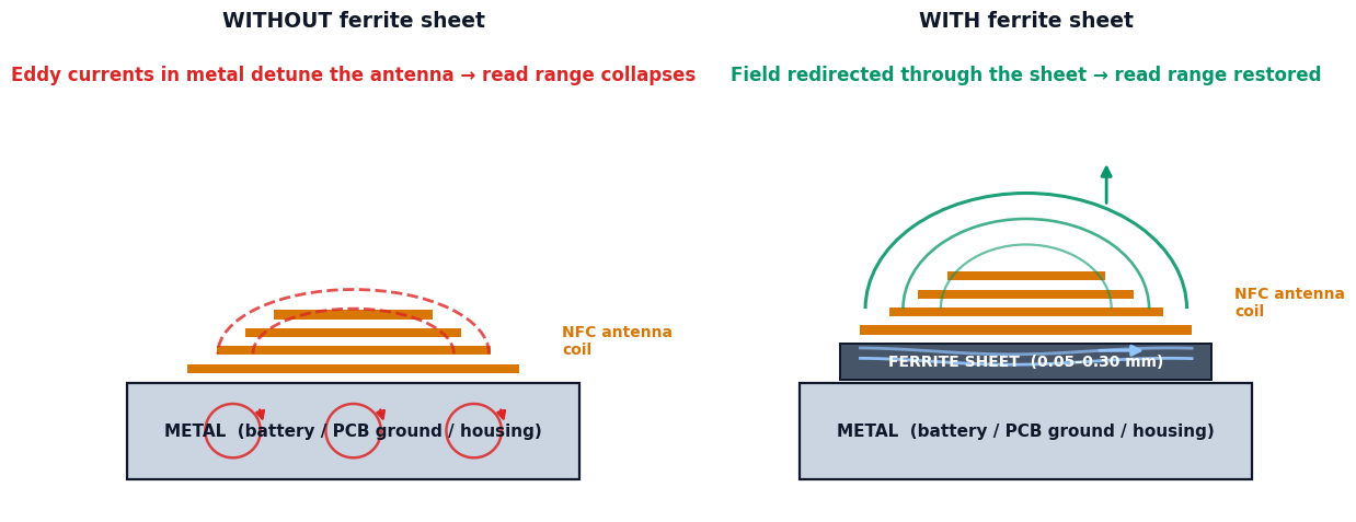
NFC runs at 13.56 MHz using magnetic near-field coupling. When the antenna's alternating magnetic field hits a conductive surface — a battery, a PCB ground plane, a metal housing — it induces eddy currents in the metal. Those eddy currents generate an opposing field that detunes the antenna: inductance drops, resonance shifts, and the energy meant for the tag never gets there.
The thinner your product, the worse it gets, because the antenna sits closer to the metal. This is why the problem shows up so often in phones, wearables, smart locks, payment terminals and access readers — slim devices with metal everywhere.
What the Ferrite Sheet Actually Does
A ferrite sheet placed between antenna and metal gives the magnetic flux a low-reluctance path: instead of penetrating the metal, the field lines travel through the sheet, parallel to the surface, and close the loop without inducing eddy currents. The antenna keeps its designed inductance and the read range comes back.
Two material properties decide whether a sheet can do this at 13.56 MHz:
- Real permeability μ′ — how well the sheet conducts flux. Higher μ′ redirects more field
- Magnetic loss μ″ — how much energy the sheet burns as heat. At 13.56 MHz you want μ″ low; lossy material would eat the signal you are trying to save
Redirect or absorb? NFC ferrite sheets are flux redirectors (high μ′, low μ″ at 13.56 MHz). Broadband EMI absorber sheets are the opposite — high loss, turning noise into heat at 100 MHz–3 GHz. Same-looking black sheet, opposite job. Using an absorber behind an NFC antenna will make things worse. See the full map on our Electronics & EMI page.
Choosing Thickness: 0.05–0.30 mm
Thicker sheets redirect flux better — but they add stack height in products that have none to spare. The practical selection logic:
| Thickness | Typical use | Note |
|---|---|---|
| 0.05–0.08 mm | Cards, tags, ultra-slim readers | Minimum viable shielding; check read range carefully |
| 0.08–0.15 mm | Phones, wearables, TWS earbuds, hearing aids | The sweet spot for most consumer antennas |
| 0.15–0.30 mm | POS terminals, access readers, industrial devices | More margin where space allows |
Typical values for material selection reference — final choice should be verified on your actual device.
The rule that saves projects: choose the thinnest sheet that restores your target read range — not the thickest one that fits. Every extra 0.05 mm you don't need is stack height and cost you keep forever.
Permeability at 13.56 MHz
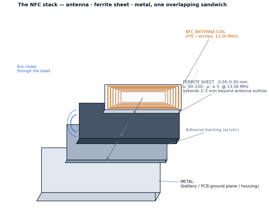
For NFC flux redirection, look for μ′ roughly in the 50–150 range at 13.56 MHz with low loss (μ″ ≤ 5 at the same frequency). Beware of datasheets quoting permeability at 1 kHz — permeability falls with frequency, and a sheet that looks superb at low frequency may be mediocre at 13.56 MHz. Always compare values at your operating frequency.
Standard sheets ship with acrylic adhesive backing and optional PET cover film; die-cut rings, frames and complex outlines are routine. Sheets are non-magnetized — they ship as regular goods, no magnetic inspection, no special air-freight handling.
Mounting: Where Good Sheets Go to Fail
- Cover beyond the antenna outline — extend the sheet at least 2–3 mm past the antenna trace on all sides; flux escapes around the edges of an undersized sheet
- No air gaps — the sheet must sit flat against both antenna and metal; air is a reluctance you didn't design for
- Don't fold across its plane — flexible ferrite bends in one direction; creasing cracks the ferrite layer and kills local permeability
- Mind the whole stack — battery shields, metal frames and conductive coatings all count as "metal"; test in the final housing, not on the bench bare board
The 5-Minute Bench Check
Before freezing the design: place your antenna on the actual metal surface, measure read range with your reader (or a phone). Then slide the candidate sheet between antenna and metal and measure again. A correct sheet typically restores read range to near the free-air value. If it doesn't, change thickness before changing anything else — and if two candidates both work, pick the thinner one.